In this article I will explain you how to configure and use SPI interface on CH32V003 MCU. It has one Full Duplex SPI Interface which can be used as SPI master or in Slave mode.
In this article, I will explain how to use SPI in the full duplex master mode.
SPI pins on CH32V003
- MISO (Master In Slave Out) – PC7
- MOSI (Master Out Slave In) – PC6
- CLOCK – PC5
- CS (Chip Select) – Hardware controlled CS/NSS – PC1, Software controlled any GPIO could be used as user code will control the CS pin logic.
CH32V003 comes in various IC packages, please check SPI pins availability before using it into your application circuit. SPI pins are not available on any other pins than mentioned above.

In order to configure the SPI interface, you need to configure the GPIOs and then setting of the SPI like mode, clock speed, etc.
Here is the SPI setting function, in this example I have used software control for CS and used GPIOC Pin3 for CS.
/* SPI Mode Definition */
#define HOST_MODE   0
#define SLAVE_MODE   1

/* SPI Communication Mode Selection */
#define SPI_MODE   HOST_MODE

#define SPI_CS_PIN                  GPIO_Pin_3
#define SPI_CS_PORT                 GPIOC

void SPI_FullDuplex_Init(void)
{
    GPIO_InitTypeDef GPIO_InitStructure={0};
    SPI_InitTypeDef SPI_InitStructure={0};

    RCC_APB2PeriphClockCmd( RCC_APB2Periph_GPIOC | RCC_APB2Periph_SPI1, ENABLE );

    GPIO_InitStructure.GPIO_Pin = GPIO_Pin_3;
        GPIO_InitStructure.GPIO_Mode = GPIO_Mode_Out_PP;
        GPIO_InitStructure.GPIO_Speed = GPIO_Speed_50MHz;
        GPIO_Init( GPIOC, &GPIO_InitStructure );

#if (SPI_MODE == HOST_MODE)
    GPIO_InitStructure.GPIO_Pin = GPIO_Pin_5;
    GPIO_InitStructure.GPIO_Mode = GPIO_Mode_AF_PP;
    GPIO_InitStructure.GPIO_Speed = GPIO_Speed_50MHz;
    GPIO_Init( GPIOC, &GPIO_InitStructure );

    GPIO_InitStructure.GPIO_Pin = GPIO_Pin_7;
    GPIO_InitStructure.GPIO_Mode = GPIO_Mode_IN_FLOATING;
    GPIO_Init( GPIOC, &GPIO_InitStructure );

    GPIO_InitStructure.GPIO_Pin = GPIO_Pin_6;
    GPIO_InitStructure.GPIO_Mode = GPIO_Mode_AF_PP;
    GPIO_InitStructure.GPIO_Speed = GPIO_Speed_50MHz;
    GPIO_Init( GPIOC, &GPIO_InitStructure );

#elif (SPI_MODE == SLAVE_MODE)
    GPIO_InitStructure.GPIO_Pin = GPIO_Pin_5;
    GPIO_InitStructure.GPIO_Mode = GPIO_Mode_IN_FLOATING;
    GPIO_Init( GPIOC, &GPIO_InitStructure );

    GPIO_InitStructure.GPIO_Pin = GPIO_Pin_7;
    GPIO_InitStructure.GPIO_Mode = GPIO_Mode_AF_PP;
    GPIO_InitStructure.GPIO_Speed = GPIO_Speed_50MHz;
    GPIO_Init( GPIOC, &GPIO_InitStructure );

    GPIO_InitStructure.GPIO_Pin = GPIO_Pin_6;
    GPIO_InitStructure.GPIO_Mode = GPIO_Mode_IN_FLOATING;
    GPIO_Init( GPIOC, &GPIO_InitStructure );

#endif

    SPI_InitStructure.SPI_Direction = SPI_Direction_2Lines_FullDuplex;

#if (SPI_MODE == HOST_MODE)
    SPI_InitStructure.SPI_Mode = SPI_Mode_Master;

#elif (SPI_MODE == SLAVE_MODE)
    SPI_InitStructure.SPI_Mode = SPI_Mode_Slave;

#endif

    SPI_InitStructure.SPI_DataSize = SPI_DataSize_8b;
    SPI_InitStructure.SPI_CPOL = SPI_CPOL_Low;
    SPI_InitStructure.SPI_CPHA = SPI_CPHA_2Edge;
    SPI_InitStructure.SPI_NSS = SPI_NSS_Soft;
    SPI_InitStructure.SPI_BaudRatePrescaler = SPI_BaudRatePrescaler_256;
    SPI_InitStructure.SPI_FirstBit = SPI_FirstBit_MSB;
    SPI_InitStructure.SPI_CRCPolynomial = 7;
    SPI_Init( SPI1, &SPI_InitStructure );

    SPI_Cmd( SPI1, ENABLE );
}
In order to send the SPI data following code is used, basically you put the data in the register and the SPI module send out the data on MOSI pin. You need to wait till data register is empty to make sure earlier transfer is completed.
#define SPI_DELAY                   100

void SPISendBytes(uint8_t *sendData, uint32_t length)
{
    uint32_t loop = 0;
    uint8_t tmp = 0;
    for(loop = 0; loop < length; loop++)
    {
        //Send SPI Byte
        while( SPI_I2S_GetFlagStatus( SPI1, SPI_I2S_FLAG_TXE ) == RESET ); // wait while flag is zero or TX buffer not empty
        SPI_I2S_SendData( SPI1, sendData[loop] );

        //Receive SPI Byte
        while(SPI_I2S_GetFlagStatus( SPI1, SPI_I2S_FLAG_RXNE ) == RESET ); // wait while flag is zero or RX buffer is empty
        tmp = SPI_I2S_ReceiveData( SPI1 );
    }

}
In order to receive the data over SPI, following code will be used
void SPIReceiveBytes(uint8_t *getData, uint32_t length)
{
    uint32_t loop = 0;
    for(loop = 0; loop < length; loop++)
    {
        //Send SPI Byte
        while( SPI_I2S_GetFlagStatus( SPI1, SPI_I2S_FLAG_TXE ) == RESET ); // wait while flag is zero or TX buffer not empty
        SPI_I2S_SendData( SPI1, 0x00 );

        //Receive SPI Byte
        while(SPI_I2S_GetFlagStatus( SPI1, SPI_I2S_FLAG_RXNE ) == RESET ); // wait while flag is zero or RX buffer is empty
        getData[loop] = SPI_I2S_ReceiveData( SPI1 );

    }

}
and in many situations, you will need to send the data and at the same time while you are sending, you will get the data also from the device which you need to capture. So, for that the following code will be used.
void SPISendReceiveBytes(uint8_t *sendData, uint8_t *getData, uint32_t length)
{
    uint32_t loop = 0;
    for(loop = 0; loop < length; loop++)
    {
        //Send SPI Byte
        while( SPI_I2S_GetFlagStatus( SPI1, SPI_I2S_FLAG_TXE ) == RESET ); // wait while flag is zero or TX buffer not empty
        SPI_I2S_SendData( SPI1, sendData[loop] );

        //Receive SPI Byte
        while(SPI_I2S_GetFlagStatus( SPI1, SPI_I2S_FLAG_RXNE ) == RESET ); // wait while flag is zero or RX buffer is empty
        getData[loop] = SPI_I2S_ReceiveData( SPI1 );

    }
}
I have connected SPI NOR Flash(Winbond 25Q080) on my development board and the following code is used to read the Flash ID and Read data from the memory.
void SPIFlashReadID(uint8_t *spiFlashID)
{

    uint8_t txBuf[4] = {0};

    txBuf[0] = 0x9F;
    txBuf[1] = 0x00;
    txBuf[2] = 0x00;
    txBuf[3] = 0x00;

    GPIO_ResetBits(SPI_CS_PORT, SPI_CS_PIN); // CS LOW

    SPISendReceiveBytes(txBuf, spiFlashID, 4);

    GPIO_SetBits(SPI_CS_PORT, SPI_CS_PIN); // CS HIGH
}
I use the Saleae Logic’s logic analyzer to capture the waveform to see what data I am getting. You can see I have sent 0x9F command and received 0xEF, 0X40 and 0x14 as the data.

void SpiFlashReadData(uint32_t startAddress, uint8_t *data, uint32_t length)
{
uint8_t txBuf[4] = {0};
txBuf[0] = SPI_FLASH_READ_DATA;
txBuf[1] = startAddress >> 16;
txBuf[2] = startAddress >> 8;
txBuf[3] = startAddress;
GPIO_ResetBits(SPI_CS_PORT, SPI_CS_PIN); // CS LOW
SPISendBytes(txBuf, 4);
SPIReceiveBytes(data, length);
GPIO_SetBits(SPI_CS_PORT, SPI_CS_PIN); // CS HIGH
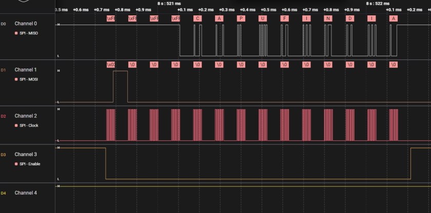
}Here is the capture of reading 10 bytes from the memory.
“CAPUFINDIA” was written on the SPI Flash and in the waveform below you can see same read out.
That’s all for setting SPI Master Interface on CH32V003 microcontroller and how to use it.
More examples will be published soon. You can follow the main CH32V003 Tutorial Page. I hope you found article useful and able to follow easily.
I am currently working as an embedded systems design consultant helping companies build custom embedded products and develop test automation solutions for their PCB.
If you have any feedback about the blog, you can share it in the comments below or contact me directly.