Already popular CH32V003 MCU has one I2C block on the MCU which can be used to connect different I2C devices on the hardware.

What is I2C Interface?
The Inter-Integrated Circuit (I2C) interface is a serial communication protocol that allows two or more integrated circuits (ICs) to communicate with each other. It is a two-wire interface, meaning that it only requires two wires to communicate: a clock line (SCL) and a data line (SDA).
I2C is a relatively simple protocol, making it easy to implement in hardware and software. It is also a very versatile protocol, and can be used to connect a wide variety of devices, including microcontrollers, sensors, and actuators.
One of the most common uses of I2C is to connect a microcontroller to a peripheral device, such as a memory chip (EEPROM) or a display(Character LCD, OLED, etc.). I2C can also be used to connect multiple microcontrollers together, allowing them to communicate with each other and share data.
Configuring I2C on CH32V003
WCH Electronics has provided examples projects and it is easy to follow and if you have doubts you can ask them over email.
I referred their I2C_EEPROM example to understand how to configure and use I2C interface on CH32V003 MCU.
In order to configure I2C, you need to enable clock of GPIO Port, I2C, select the pins in alternate function and open drain mode and then configure I2C parameters like Baud rate, 7/10 bit address, etc.
Let us see how to do that in the code
in the example given below, GPIO C1 is configured as SDA and GPIO C2 as SCL.
IIC_Init function takes two parameters, one is baud rate and other is Slave/DeviceAddress.
void IIC_Init(u32 bound, u16 address)
{
    GPIO_InitTypeDef GPIO_InitStructure={0};
    I2C_InitTypeDef I2C_InitTSturcture={0};

    RCC_APB2PeriphClockCmd( RCC_APB2Periph_GPIOC | RCC_APB2Periph_AFIO, ENABLE );
    RCC_APB1PeriphClockCmd( RCC_APB1Periph_I2C1, ENABLE );

    GPIO_InitStructure.GPIO_Pin = GPIO_Pin_2;
    GPIO_InitStructure.GPIO_Mode = GPIO_Mode_AF_OD;
    GPIO_InitStructure.GPIO_Speed = GPIO_Speed_50MHz;
    GPIO_Init( GPIOC, &GPIO_InitStructure );

    GPIO_InitStructure.GPIO_Pin = GPIO_Pin_1;
    GPIO_InitStructure.GPIO_Mode = GPIO_Mode_AF_OD;
    GPIO_InitStructure.GPIO_Speed = GPIO_Speed_50MHz;
    GPIO_Init( GPIOC, &GPIO_InitStructure );

    I2C_InitTSturcture.I2C_ClockSpeed = bound;
    I2C_InitTSturcture.I2C_Mode = I2C_Mode_I2C;
    I2C_InitTSturcture.I2C_DutyCycle = I2C_DutyCycle_2;
    I2C_InitTSturcture.I2C_OwnAddress1 = address;
    I2C_InitTSturcture.I2C_Ack = I2C_Ack_Enable;
    I2C_InitTSturcture.I2C_AcknowledgedAddress = I2C_AcknowledgedAddress_7bit;
    I2C_Init( I2C1, &I2C_InitTSturcture );

    I2C_Cmd( I2C1, ENABLE );

    I2C_AcknowledgeConfig( I2C1, ENABLE );
}
Once the I2C configuration is done we need to see how to Read and Write to an EEPROM. For testing I have used a AT24C256 Memory breakout board
Four connection are required to be connected with CH32V003 Development Board, I2C SCL, I2C SDA, 3.3V, GND.
Separate Connection of 3.3V, SWIO, GND is required from the WCH-LinkE Debugger/Programmer. For my experiment I have used programmer power supply to power the development board and Memory Breakout Board.

Now, to interface any I2C device we need to understands the protocol, how the data transfer happens from Master to Slave and from Slave to Master both ways.
I will not get into details of I2C Protocol as I would assume you will learn or already have an understand of how I2C works. Otherwise you can learn from this I2C tutorial.
EEPROM is Memory device which has I2C Interface. We will see how to read and write to I2C EEPROM Memory. So, What are the steps required to read and write to EEPROM?
READ EEPROM Operation Break up: Start + 0xA0(Device Address + Read/Write Bit) + 8/16bit Data Address + Start + 0xA1(Device Address + Read/Write Bit) + Read Data + Stop.
WRITE EERPOM Operation Break up: Start + 0xA0 + 8/16bit Data Address + Write Data + Stop.
Code will be as shown below:
Single Byte Read Command
u8 AT24CXX_ReadOneByte(u16 ReadAddr)
{
    u8 temp=0;

    while( I2C_GetFlagStatus( I2C1, I2C_FLAG_BUSY ) != RESET );
    I2C_GenerateSTART( I2C1, ENABLE );

    while( !I2C_CheckEvent( I2C1, I2C_EVENT_MASTER_MODE_SELECT ) );
    I2C_Send7bitAddress( I2C1, 0XA0, I2C_Direction_Transmitter );

    while( !I2C_CheckEvent( I2C1, I2C_EVENT_MASTER_TRANSMITTER_MODE_SELECTED ) );

#if (Address_Lenth  == Address_8bit)
    I2C_SendData( I2C1, (u8)(ReadAddr&0x00FF) );
    while( !I2C_CheckEvent( I2C1, I2C_EVENT_MASTER_BYTE_TRANSMITTED ) );

#elif (Address_Lenth  == Address_16bit)
    I2C_SendData( I2C1, (u8)(ReadAddr>>8) );
    while( !I2C_CheckEvent( I2C1, I2C_EVENT_MASTER_BYTE_TRANSMITTED ) );

    I2C_SendData( I2C1, (u8)(ReadAddr&0x00FF) );
    while( !I2C_CheckEvent( I2C1, I2C_EVENT_MASTER_BYTE_TRANSMITTED ) );

#endif

    I2C_GenerateSTART( I2C1, ENABLE );

    while( !I2C_CheckEvent( I2C1, I2C_EVENT_MASTER_MODE_SELECT ) );
    I2C_Send7bitAddress( I2C1, 0XA0, I2C_Direction_Receiver );

    while( !I2C_CheckEvent( I2C1, I2C_EVENT_MASTER_RECEIVER_MODE_SELECTED ) );
  while( I2C_GetFlagStatus( I2C1, I2C_FLAG_RXNE ) ==  RESET )
    I2C_AcknowledgeConfig( I2C1, DISABLE );

    temp = I2C_ReceiveData( I2C1 );
  I2C_GenerateSTOP( I2C1, ENABLE );

    return temp;
}
Single Byte Write Command
void AT24CXX_WriteOneByte(u16 WriteAddr, u8 DataToWrite)
{
    while( I2C_GetFlagStatus( I2C1, I2C_FLAG_BUSY ) != RESET );
    I2C_GenerateSTART( I2C1, ENABLE );

    while( !I2C_CheckEvent( I2C1, I2C_EVENT_MASTER_MODE_SELECT ) );
    I2C_Send7bitAddress( I2C1, 0XA0, I2C_Direction_Transmitter );

    while( !I2C_CheckEvent( I2C1, I2C_EVENT_MASTER_TRANSMITTER_MODE_SELECTED ) );

#if (Address_Lenth  == Address_8bit)
    I2C_SendData( I2C1, (u8)(WriteAddr&0x00FF) );
    while( !I2C_CheckEvent( I2C1, I2C_EVENT_MASTER_BYTE_TRANSMITTED ) );

#elif (Address_Lenth  == Address_16bit)
    I2C_SendData( I2C1, (u8)(WriteAddr>>8) );
    while( !I2C_CheckEvent( I2C1, I2C_EVENT_MASTER_BYTE_TRANSMITTED ) );

    I2C_SendData( I2C1, (u8)(WriteAddr&0x00FF) );
    while( !I2C_CheckEvent( I2C1, I2C_EVENT_MASTER_BYTE_TRANSMITTED ) );

#endif

    if( I2C_GetFlagStatus( I2C1, I2C_FLAG_TXE ) !=  RESET )
    {
        I2C_SendData( I2C1, DataToWrite );
    }

    while( !I2C_CheckEvent( I2C1, I2C_EVENT_MASTER_BYTE_TRANSMITTED ) );
    I2C_GenerateSTOP( I2C1, ENABLE );
}
With Single byte read and write we can create multiple byte read/write function by calling them in loop for no of bytes we need to read/write times.
/*********************************************************************
* @fn AT24CXX_Read
*
* @brief Read multiple data from EEPROM.
*
* @param ReadAddr - Read frist address. (AT24c02: 0~255)
* pBuffer - Read data.
* NumToRead - Data number.
*
* @return none
*/
void AT24CXX_Read(u16 ReadAddr, u8 *pBuffer, u16 NumToRead)
{
while(NumToRead)
{
*pBuffer++=AT24CXX_ReadOneByte(ReadAddr++);
NumToRead--;
}
}
/*********************************************************************
* @fn AT24CXX_Write
*
* @brief Write multiple data to EEPROM.
*
* @param WriteAddr - Write frist address. (AT24c02: 0~255)
* pBuffer - Write data.
* NumToWrite - Data number.
*
* @return none
*/
void AT24CXX_Write(u16 WriteAddr, u8 *pBuffer, u16 NumToWrite)
{
while(NumToWrite--)
{
AT24CXX_WriteOneByte(WriteAddr,*pBuffer);
WriteAddr++;
pBuffer++;
Delay_Ms(2);
}
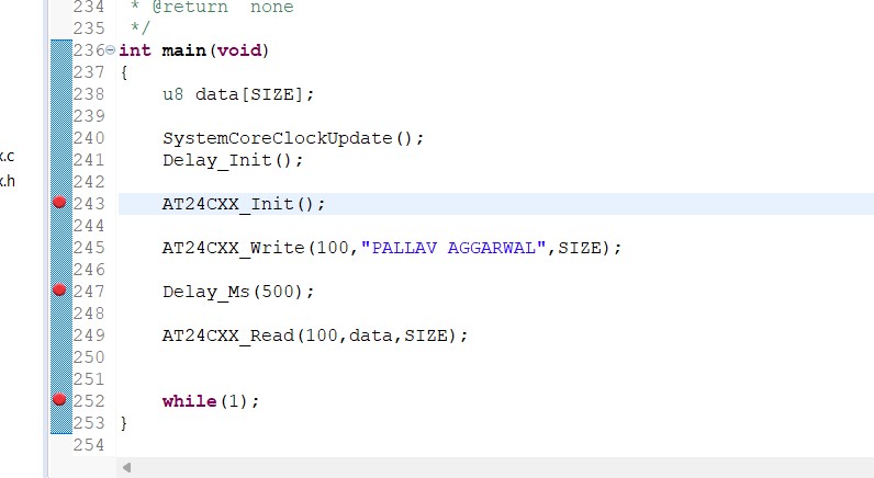
}In the main function I have used like this to test:
int main(void)
{
    u8 data[SIZE];

    SystemCoreClockUpdate();
    Delay_Init();

    AT24CXX_Init();

    AT24CXX_Write(100,"PALLAV AGGARWAL",SIZE);

    Delay_Ms(500);

    AT24CXX_Read(100,data,SIZE);


    while(1);
}
What I did is, added breakpoint after write function and the after read function and verified whatever I wrote in the Memory is what I got read back from the memory or not.
I hope it is now clear how to use I2C on this MCU.
If you understand how to break I2C communication with a device into different parts like Start, Device Address, Send Data, Stop, it will be very easy for you to understand and interface with any I2C device.
In my up coming example I will interface Sensiron’s SHTC3 Temperature Humidity Sensor on I2C and show you how to write code for that.
I hope this article was useful.
See also:
- Setting up the Development Environment for CH32V003: Compile and Run first example code
- CH32V003: GPIO as Output
- CH32V003: GPIO as Input (Polling, Interrupt)
- CH32V003: UART Transmit / Receive data
- CH32V003: PWM output
- CH32V003: How to use an ADC
- CH32V003: How to use I2C
- CH32V003: How to use SPI
- CH32V003: Timer based Periodic Interrupt
- CH32V003: How to read 64-bit Unique ID
I am currently working as an embedded systems design consultant and helping companies build custom embedded products, develop test automation solution for their PCB.
If you have any feedback about the blog, you can share in the comments below or you can also contact me directly.