As the winter starts, pollution become high and there is an increased sale of CO2 monitor, air purifier, etc. especially in the cities which are high polluted.
A couple of days back I bought this InkBirdPlus Co2 Monitor to keep a check on the ventilation in the place where I work.
Any electronics coming to my hand and I don’t open :), that’s not possible.
I quickly opened to see what has inside this CO2 monitor. I purchased it from Amazon and it costed a bit less than 6000 Indian rupees.

In the package you get a USB-A to USB-C cable for charging/power and the CO2 Monitor device itself.
Device looks pretty with very nice finish and a large glass display, you can easily read from a distance.
On the display, you have CO2 reading, based on the value it also gives you indication that the environment is good, bad or moderate which is really useful for a layman.
Other than Co2, it displays temperature and humidity as well.
On the top right corner of the display it shows speaker icon, which tell if buzzer is enabled or not and the status of the battery (3 bar means battery fully charged).
On the top, 3 buttons are there to control temperature unit (Fahrenheit or Centigrade), buzzer enable/disable, display ON/OFF.
It is powered by a single cell lithium battery.


On the PCB if you look closely, you will see USB C connector which is mainly for charging the battery.
3.3V is generated using the LDO regulator (LR33B) onboard which powers all the peripherals like MCU, buzzer, CO2 Sensor, Temperature/Humidity sensor.

LQFP48 package MCU is used, the part number is removed by the laser but probably a Low Cost GD32 or STM32 MCU.
Any basic MCU with I2C, UART, a few GPIO is good enough for this kind of application.

Another DC DC converter is used, SMD marking SC8ND, it is not very clear why they have used this in the circuitry.
It could be a boost converter to boost battery voltage so that to give 3.3V LDO stable input voltage irrespective of battery voltage level.
I don’t it is a buck boost converter, which would have been better in this case. If you know details about this circuit, please share with me.

The below you see is the CO2 Sensor module. There is no marking on any side of the sensor but looks like a MH-Z19E or a similar sensor.

For battery charging, it is using TP4056 linear charger IC.
You can also see a buzzer driven by a transistor/Mosfet.

what you see below is three switches on the PCB, it also has a temperature/humidity sensor connected separately with the main PCB using a cable. Separate cable is there for temperature humidity sensor and for the keys.
I would have tried to make it one, easy for assembly. More connector means more issues.
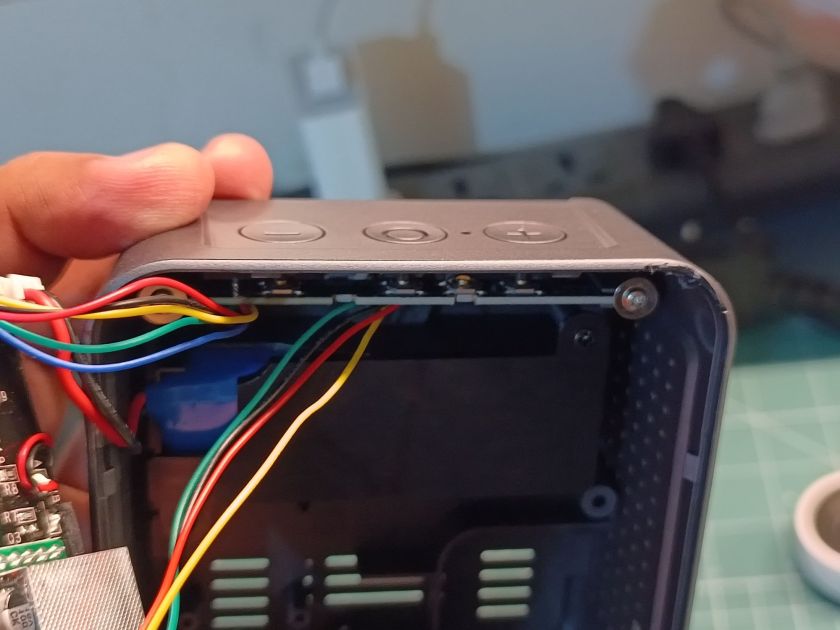


And, the glass display. It is connected to the PCB using rubber having conductive pads and the pads on the PCB with the help of which connection to the display are made.

On the PCB, there is an option for U15, looks like an ESP8266 module for another variant with Wi-Fi connectivity.
I hope you found this teardown useful and learned something new today!
If you have any questions please ask in the comments section below, I will try to respond as soon as possible.
You can read other teardown blogs and watch teardown videos.
I am currently working as an embedded systems design consultant and helping companies build custom embedded products, develop test automation solution for their PCB or complete product.
If you have any feedback about the blog, you can share in the comments below or you can also contact me directly.
Read more interesting articles on Embedded Systems Design.