

I have been using Alexa since many years now at home and always wondered how it works. Although, over all I know how it works but form electronics point of view I wasn’t sure of what is really take to create such a device.
Recently, when I found Amazon Echo Dot was available at a discount, without any delay I ordered one for a teardown.
Here is what I found inside Amazon Echo Dot (3rd Generation).
Inside the box you will get a Adapter which is 230V to 12V DC, User manual and the Echo Dot device itself.
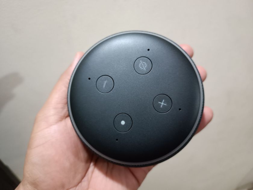
TOP Side
From the top device looks like this, You have 4 buttons, one for power, two for volume up and down and another one is for mute. You can see 4 holes, they are for MIC.

Back Side
Nothing much on the back side other than serial number, bar code, marking of various certifications, etc.
One need to remove this cover in order to get access to the device.

After removing the cover, this what you get, further 4 screws need to removed to get access to the processor PCB and Speaker.

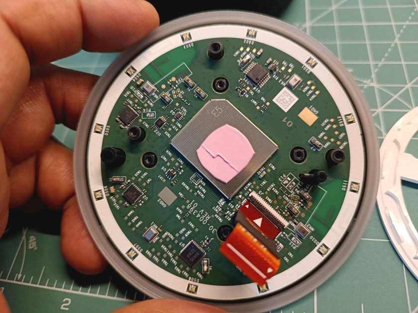
Main Controller PCB
Inside the enclosure you can see a QR code is there and a RFID tag is used, most probably to track the device while it is moving from one station to other on the assembly floor.

Here is the main Processor board, on the top side all power supply related components and there, the main processor is on the other of the PCB.


This is the NAND Flash Memory from Micron (NW943)


This is DDR3 RAM from Samsung (K4B2G16)

Main processor used is MediaTek MT8516 which is a highly integrated, application processing platform for Cloud-connected voice assistant devices.

Audio Amplifier used for speaker is Texas Instruments TAS5770


P1, P2 are spring loaded pins which connects to pads given in the speaker compartment from where it connects to the speaker.
L10, L11 along with capacitor are basically LCD filter.

And this is where a single speaker is located.


TOP PCB with MIC/WI-FI/BLE
And below is the TOP PCB which has all the electronics related to MIC, LEDs, Keys, Dual Band Wi-Fi and Bluetooth Controller. Both boards are connected together via FPC cable.


You can see in the image below 2 dome switches, U11 is basically ambient light sensor.


Mediatek MT7658 is used as Dual Band Wi-Fi and Bluetooth controller.

4x Analog Microphones are connected to Stereo ADC from Texas Instruments TLV320ADC3101 basically two MIC goes to one ADC3101.


U7 3236A is RGB LED driver IC from Lumissil Microsystems, full part number is IS31FL3236A

Amazon Echo Dot Teardown Video if you like the video format

I hope you found this teardown useful and learned something new today!
If you have any questions please ask in the comments section below, I will try to respond as soon as possible.
I am currently working as an embedded systems design consultant and helping companies build custom embedded products, develop test automation solution for their PCB or complete product.
If you have any feedback about the blog, you can share in the comments below or you can also contact me directly.
Read more interesting articles on Embedded Systems Design.