

Paytm has now released next generation soundbox V2.0 in the market with an improved design.
Good thing about Paytm Soundbox V2.0 is that, they are designed and manufactured by an Indian company Oakter. They have manufacturing plant in Noida.
Thanks to Oakter for sending me the units for the teardown.

Paytm Soundbox V2.0 has two variants one is with 2G connectivity and another one is with 4G.
In this blog, I will show you both the design and internals, hope you will enjoy all the details and learn something new from it.
Subscribe to my blog
PayTM SoundBox 2.0 (4G Version)
This version has a small box for the whole electronics and the QR code plate attaches to the enclosure using a slide mechanism. See in the images below.


When you open the box, you can see, it has all the electronics on a single PCB, which is a neat design.
Very important for a high volume production, many a times splitting PCBs increases flexibility but in case of mass manufacturing it adds up cost in managing multiple parts and assembling it together.
This is what you see inside the enclosure:


You can see it uses a single cell lithium battery connected to the PCB with a two pin cable.
Various Sections are:
Battery charger and protection where TP4056 linear battery charger circuit with DW01 and mosfet (8205A) is used for protection.

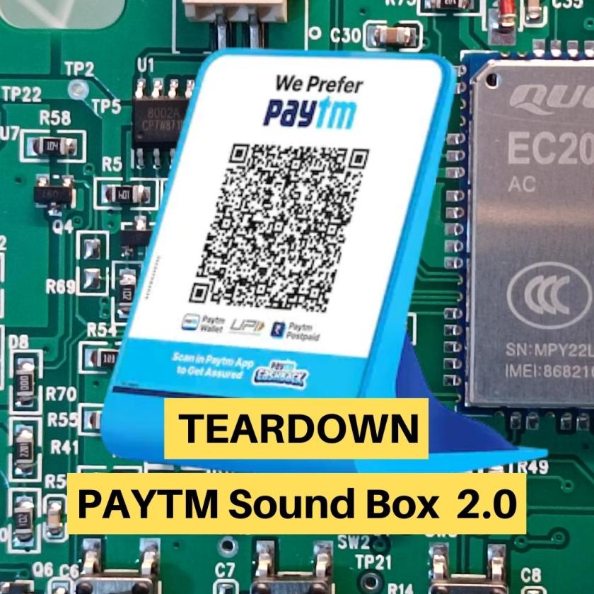
Quectel EC200U is used as the GPRS modem with microcontroller where you can write the application code as well so no external MCU is required. This keeps cost and complexity really low.
Audio, SD Card, RGB LED(D1), Keys(SW1-4), everything is interfaced with EC200U only.
Switch/Keys are provided so that user can increase the audio volume, power ON/OFF the device and one for listening to the last transaction.
UFL connector is used for connecting GPRS Antenna which is an external antenna (PCB with RF cable, you can see in the image above)
Left bottom side, J4 is given for programming.
This is the PCB where all the electronics is there.

Audio signals are generated directly from EC200U with an external amplifier (8002A ).


On the back side of the PCB, you see the SD card(J5), SW5 which is a reset switch, J6 which is SIM connector and a USB C connector for 5V Power Input for charging the battery and powering the board.

You see in the image below how Speaker(4 Ohm 2W) is enclosed in a separate compartment.

A short video on Paytm Soundbox 2.0 (4G Variant) Teardown

Paytm SoundBox 2.0 (2G Version)
You can see 2G version is a little different. Two main difference are it has 2G gprs modem and it has LCD on the back side. See the images below:


once you open the box you see the main PCB which has all the electronics, single lithium battery.


LCD is a 16×2 character LCD with white backlight connected over I2C interface. You can see 4 wire cable going from main PCB to the LCD display. On the Display one controller is there which take the data over I2C interface and drives the LCD.


And here is the Main PCB where Quectel MC66 which is 2G modem but also acts a main controller for the whole application.


All the other features like Battery charging, battery deep discharge protection, programming interface, RGB LED, Keys, Speaker amplifier, etc. all are same as detailed above in the Paytm SoundBox 4G section.
5V 1A Charger is provided with the soundbox which has USB C connector.

Short Video on Paytm Sound box 2.0 (2G Variant)

I hope you found this teardown useful and learned something new today!
If you have any questions please ask in the comments section below, I will try to respond as soon as possible.
I am currently working as an embedded systems design consultant and helping companies build custom embedded products, develop test automation solution for their PCB or complete product.
If you have any feedback about the blog, you can share in the comments below or you can also contact me directly.
Read more interesting articles on Embedded Systems Design.